Description
Here’s the information on the elusive APC smart signalling protocol used by their higher end units (Back-UPS Pro, Smart-UPS, Matrix-UPS, etc). What you see here has been collected from a variety of sources. Some people analyzed the chatter between PowerChute and their hardware. Others sent various characters to the UPS and figured out what the results meant.
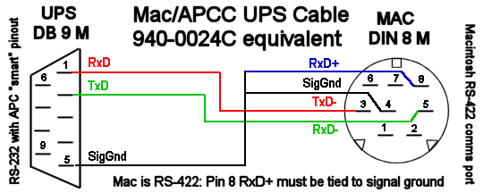
RS-232 differences
Normal 9 pin serial connections have TxD on 3 and RxD on 2. APC’s smart serial ports put TxD on pin 1 and RxD on pin 2. This means you go nowhere if you use a normal straight through serial cable. In fact, you might even power down the load if you plug one of those cables in. This is due to the odd routing of pins - DTR and RTS from the PC usually wind up driving the on/off line. So, when you open the port, they go high and *poof* your computer dies.
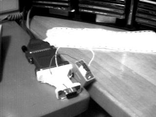
Originally this evil hack was used to connect the UPS to the PC when this page was first being built. As you can see, I cheated and neglected the ground (only 2 wires!) and it still worked. This method can be used for playing around, but for professional systems this is obviously not a viable option.
That hack didn’t work out so well (damned cats), so it was retired quite awhile back. The most practical solution was to go out and BUY the DOS/Win version of Powerchute just for the black (smart) cable. I recommend doing the same thing if you actually care about this thing working properly. Of course, if you have one of the newer packages that came with PowerChute, you already have the cable you need.
Cable hacking
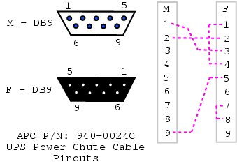
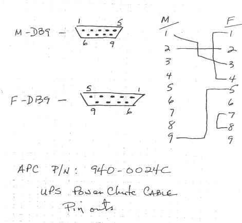
If you are handy with cable tools, check out these diagrams. They show how to clone the black "smart" cable that’s normally provided with APC models sold after 1996. The loopback pins (back to the PC) are used to keep PowerChute happy by allowing cable detection. If you use the NUT apcsmart or newapc drivers, those pins don’t matter.
The Smart Protocol
Despite the lack of official information from APC, this table has been constructed.
It’s standard RS-232 serial communications at 2400 bps/8N1.
Don’t rush the UPS while transmitting or it may stop talking to you.
This isn’t a problem with the normal single character queries, but it really does matter for multi-char things like "@000".
Some newer units also appear to support two-byte command sequences (for example, 9F D2) in addition to the single-character commands listed here.
These two-byte commands may also work on SPRM and SRVS series units, since they appear to share the same bundled CD management software.
Sprinkle a few calls to usleep() in your code and everything will work a lot better.
| Character | Meaning | Typical results | Other info | ||||||
|---|---|---|---|---|---|---|---|---|---|
|
Model string |
|
Spotty support for this query on older models |
||||||
|
Turn on UPS |
n/a |
Send twice with > 1.5s delay between chars Only on 3rd gen SmartUPS and Black Back-UPS Pros |
||||||
|
Capability string |
(long string) |
See "Capabilities" section for more info |
||||||
|
Front panel test |
Light show + " |
Also sounds the beeper for 2 seconds |
||||||
Battery voltage |
|
This obviously varies a lot based on the current charge. Compare this to the nominal battery voltage |
|||||||
|
Internal temperature |
|
Units are degrees C |
||||||
Runtime calibration |
|
Runs until battery is below 25% (35% for Matrix) This updates the Can be aborted with a second " |
|||||||
|
Automatic selftest intervals |
|
Writable variable Values:
|
||||||
|
Line frequency, Hz |
|
If this varies much, have a word with your local electrician |
||||||
|
Cause of transfer |
|
Writable variable Values:
|
||||||
|
Measure-UPS: Alarm enable |
|
(not yet decoded)(bitmapped table, coming soon) |
||||||
|
Measure-UPS: Alarm status |
|
(not yet decoded)(bitmapped table, coming soon) |
||||||
Shutdown with grace period |
|
Send twice with > 1.5s delay between chars Older units may send " Also see grace period |
|||||||
|
Input line voltage |
|
Does not necessarily read |
||||||
|
Maximum line voltage |
|
This is the max voltage since the last time this query was run |
||||||
|
Minimum line voltage |
|
Like the one above, this one also resets itself on every query |
||||||
|
Output voltage |
|
Also see on battery output voltage |
||||||
|
Power load % |
|
Relative to the capacity of the UPS |
||||||
|
Status flags |
|
See status flags section for more info |
||||||
Turn dumb |
|
Only on 3rd gen Smart-UPS, Smart-UPS v/s, Back-UPS Pro UPS must receive command to enter smart mode continue communications after sending this |
|||||||
Soft shutdown |
|
Command executes after grace period UPS goes online when power returns Only works when on battery |
|||||||
Simulate power failure |
|
See async notifier section for info on |
|||||||
Firmware revision |
|
Can be used to determine abilities of hardware |
|||||||
|
Self test |
|
Tests battery, like pushing the test button on the front panel Also see test results entry |
||||||
Self-test results |
|
Values:
|
|||||||
Enter smart mode |
|
This must be sent before anything else on this page will work. Also see turn dumb command to exit smart mode |
|||||||
|
Shutdown immediately |
n/a |
Send twice with > 1.5s delay between chars UPS switches the load off immediately (no grace period) |
||||||
|
Protocol info |
(long string) |
Returns three main sections:
Sections are separated with a period |
||||||
|
Firmware revision |
|
Decoding above info:
|
||||||
UPS local id |
|
Writable variable Up to 8 letter identifier for keeping track of your hardware |
|||||||
Return threshold |
|
Writable variable Minimum battery charge % to return from shutdown after power returns Values:
This prevents excessive cycling during multiple power failures |
|||||||
Nominal battery voltage |
|
The battery voltage that’s expected to be present in the UPS normally Compare to the actual voltage reading |
|||||||
|
Battery level |
|
Percentage It’s much easier to use this rather than doing math on the current battery voltage and the nominal battery voltage |
||||||
|
Measure-UPS: Ambient humidity |
|
Percentage Only works on models with the Measure-UPS SmartSlot card |
||||||
|
Measure-UPS: Dry contacts |
|
Bitmapped hex variable Component values:
|
||||||
|
Estimated runtime |
|
Minutes Must be calibrated to be effective |
||||||
|
Alarm delay |
|
Writable variable Values:
Does not affect low battery warning |
||||||
|
Low transfer voltage |
|
Writable variable See capabilities to get values for a UPS UPS goes on battery after voltage drops below this point |
||||||
|
Manufacturing date |
|
Format may vary by country ( |
||||||
|
Serial number |
|
Unique for each UPS |
||||||
On-battery voltage |
|
May be a writable variable on 220/230/240 VAC units |
|||||||
Shutdown grace delay |
|
Writable variable - seconds See capabilities to read values Sets the delay before soft shutdown completes |
|||||||
|
Low battery warning |
|
Writable variable - minutes See capabilities to read values The UPS will report a low battery this many minutes before it runs out of power |
||||||
Wakeup delay |
|
Writable variable - seconds See capabilities to read values The UPS will wait this many seconds after reaching the minimum charge before returning online |
|||||||
|
Sensitivity |
|
Writable variable See capabilities to read values Meaning of values:
|
||||||
|
Upper transfer voltage |
|
Writable variable See capabilities to read values UPS goes on battery after voltage rises above this point |
||||||
|
Measure-UPS: Firmware |
|
Firmware information for Measure-UPS board |
||||||
|
Measure-UPS: Ambient temperature |
|
Degrees C Only works on models with the Measure-UPS SmartSlot card |
||||||
Last battery change |
|
Writable variable This holds whatever the user sets in it, much like the UPS local id variable |
|||||||
|
Copyright notice |
|
Only works if firmware letter is later than |
||||||
|
Reset to factory settings |
|
Resets most variables to initial factory values except identity or battery change date Not on SmartUPS v/s or BackUPS Pro |
||||||
|
Capability cycle |
(various) |
Cycle through possible capability values UPS sends |
||||||
Shutdown and return |
|
UPS shuts down after grace period with delayed wakeup after Some older models send |
|||||||
|
Abort shutdown |
|
Abort shutdown - use to abort Also known as the delete key in some places |
||||||
|
Register #1 |
n/a |
See register 1 table |
||||||
|
Register #2 |
n/a |
See register 2 table |
||||||
|
Dip switch positions |
n/a |
See dip switch table Only makes sense on models which actually have dip switches |
||||||
|
Register #3 |
n/a |
See register 3 table |
||||||
|
Line quality |
|
Values
|
||||||
|
Battery packs |
n/a |
SmartCell models: returns number of connected packs Non-SmartCell models: returns number set by user (use |
||||||
|
Measure-UPS: Upper temp limit |
|
Degrees C Writable variable Values: Use |
||||||
|
Measure-UPS: Lower temp limit |
|
Degrees C Writable variable See lower temp limit above |
||||||
|
Measure-UPS: Upper humidity limit |
|
% Writable variable Values: Use |
||||||
|
Measure-UPS: Lower humidity limit |
|
% Writable variable Values: Use |
||||||
Matrix-UPS and Symmetra commands |
|||||||||
|
Run in bypass mode |
n/a |
If online, " If already in bypass, " If UPS can’t transfer, " |
||||||
|
Number of bad battery packs |
|
Returns count of bad packs connected to the UPS |
||||||
|
Load current |
n/a |
True RMS load current drawn by UPS |
||||||
|
Apparent load power |
n/a |
Output load as percentage of full rated load |
||||||
|
Output voltage selection |
n/a |
Writable variable Values:
|
||||||
|
Front panel language |
n/a |
Writable variable Values:
|
||||||
|
Run time conservation |
n/a |
Writable variable Values:
|
||||||
The two-byte command examples (APC SPM series)
The table below shows the two-byte commands that have been observed on newer APC models such as the SPM series. These commands appear to be in addition to the single-character commands listed above, and they follow a similar format to the capability string responses, with a command character followed by a locale, number of choices, and choice length, followed by the choices themselves.
Special note: on some models (for example, SPM series), command F reports output frequency, while 9F D3 reports input line frequency. This does not match the F command description in the single-character command section above.
To change a setting over UART (turn ON or turn OFF), send commands in this sequence:
-
9F FE→ select settings operation mode; should returnOK -
9F XX→ select the setting command to change; current setting value is returned -
9F CA→ turn ON, or9F CB→ turn OFF; should returnOK -
9F FF→ confirm/save the change; should returnOK
| Character | Meaning | Typical results | Other info |
|---|---|---|---|
|
UPS rated info |
|
Appears to return VA, input/output voltage, output frequency, battery Ah, battery voltage, and one unknown extra field |
|
Running mode |
|
Observed mode values:
|
|
Input line frequency |
|
|
|
Battery current |
|
Numeric value in amps |
|
Phase lock flag |
|
Spreadsheet note: |
|
Transfer frequency range |
|
Frequency range to force transfer to battery when frequency is selected as a transfer cause |
|
ECO mode voltage range |
|
Voltage range to allow ECO mode running when ECO mode is selected as a transfer cause |
|
Status bitmap (undecoded) |
|
Bit-level meaning not yet decoded |
|
UPS alarm |
|
Writable variable. Boolean-style response ( |
|
Alarm in bypass mode |
|
Writable variable. Boolean-style response ( |
|
Auto reboot |
|
Writable variable. Boolean-style response ( |
|
Bypass when UPS is off |
|
Writable variable. Boolean-style response ( |
|
Converter mode |
|
Writable variable. Boolean-style response ( |
|
ECO mode |
|
Writable variable. Boolean-style response ( |
|
Green power function |
|
Writable variable. Boolean-style response ( |
|
Cold start |
|
Writable variable. Boolean-style response ( |
|
Bypass not allowed |
|
Writable variable. Boolean-style response ( |
Dip switch information
| Bit | Switch | Option when bit=1 |
|---|---|---|
0 |
4 |
Low battery alarm changed from 2 to 5 mins. Autostartup disabled on SU370ci and 400 |
1 |
3 |
Audible alarm delayed 30 seconds |
2 |
2 |
Output transfer set to 115 VAC (from 120 VAC) or to 240 VAC (from 230 VAC) |
3 |
1 |
UPS desensitized - input voltage range expanded |
4 - 7 |
- |
Unused at this time |
Status flags
Some common things you’ll see:
-
08= on line, battery OK -
10= on battery, battery OK -
50= on battery, battery low
| Bit | Meaning |
|---|---|
0 |
Not reported by Smart UPS v/s and BackUPS Pro |
1 |
Not reported by 1st and 2nd generation SmartUPS models |
2 |
|
3 |
|
4 |
|
5 |
|
6 |
|
7 |
|
Alert messages
| Character | Description |
|---|---|
|
Line Fail - sent when the UPS goes on-battery, repeated every 30 seconds until low battery condition reached. Sometimes occurs more than once in the first 30 seconds. |
|
Return from line fail - UPS back on line power, only sent if a |
|
Low battery - Sent to indicate low battery, but not on SmartUPS v/s or BackUPS Pro models |
|
Return from low battery - Sent when the battery has been recharged to some level only if a % has been sent previously |
|
Abnormal condition - sent for conditions such as "shutdown due to overload" or "shutdown due to low battery capacity". Also occurs within 10 minutes of turnon. |
|
Return from abnormal condition - Sent when the UPS returns from an abnormal condition where |
|
About to turn off - Sent when the UPS is about to switch off the load. No commands are processed after this character is sent. Not implemented on SmartUPS v/s, BackUPS Pro, or 3rd generation SmartUPS models. |
|
Replace battery - Sent when the UPS detects that the battery needs to be replaced. Sent every 5 hours until a new battery test is run or the UPS is shut off. Not implemented on SmartUPS v/s or BackUPS Pro models. |
|
Check alarm register for fault (Measure-UPS) - sent to signal that temp or humidity out of set limits.
Also sent when one of the contact closures changes states.
Sent every 2 minutes, stops when the alarm conditions are reset.
Only sent for alarms enabled with |
|
Variable change in EEPROM - Sent whenever any EEPROM variable is changed. Only supported on Matrix UPS and 3rd generation SmartUPS models. |
Register 1
All bits are valid on the Matrix UPS. SmartUPS models only support bits 6 and 7. Other models do not respond.
| Bit | Meaning |
|---|---|
0 |
In wakeup mode (typically lasts < 2s) |
1 |
In bypass mode due to internal fault - see register 2 or 3 |
2 |
Going to bypass mode due to command |
3 |
In bypass mode due to command |
4 |
Returning from bypass mode |
5 |
In bypass mode due to manual bypass control |
6 |
Ready to power load on user command |
7 |
Ready to power load on user command or return of line power |
Register 2
Matrix UPS models report bits 0 - 5.
SmartUPS models only support bits 4 and 6.
SmartUPS v/s and BackUPS Pro report bits 4, 6, 7.
Unused bits are set to 0.
Other models do not respond.
| Bit | Meaning |
|---|---|
0 |
Fan failure in electronics, UPS in bypass |
1 |
Fan failure in isolation unit |
2 |
Bypass supply failure |
3 |
Output voltage select failure, UPS in bypass |
4 |
DC imbalance, UPS in bypass |
5 |
Command sent to stop bypass with no battery connected - UPS still in bypass |
6 |
Relay fault in SmartTrim or SmartBoost |
7 |
Bad output voltage |
Register 3
All bits are valid on the Matrix UPS and 3rd generation SmartUPS models.
SmartUPS v/s and BackUPS Pro models report bits 0 - 5.
All others report 0 - 4.
State change of bits 1, 2, 5, 6, 7 are reported asynchronously with ? and = messages.
| Bit | Meaning |
|---|---|
0 |
Output unpowered due to shutdown by low battery |
1 |
Unable to transfer to battery due to overload |
2 |
Main relay malfunction - UPS turned off |
3 |
In sleep mode from |
4 |
In shutdown mode from |
5 |
Battery charger failure |
6 |
Bypass relay malfunction |
7 |
Normal operating temperature exceeded |
Capabilities
Upon sending a ^Z, your UPS will probably spit back something like this (truncated here for the example):
#uD43132135138129uM43229234239224uA43110112114108 ....It looks bizarre and ugly, but is easily parsed.
The # is some kind of marker/ident character.
Skip it.
The rest fits this form:
-
Command character - use this to select the value
-
Locale - use
bto find out what yours is,4applies to all -
Number of choices -
4means there are 4 possibilities coming up -
Choice length -
3means they are all 3 chars long
Then it’s followed by the choices, and it starts over.
Matrix-UPS models have ## between each grouping for some reason.
Acknowledgements
Large parts of this data were contributed or corrected by Steven Freed. This guy is some sort of APC UPS god. Many thanks.


